

Alternating current
Did you know...
Arranging a Wikipedia selection for schools in the developing world without internet was an initiative by SOS Children. Sponsor a child to make a real difference.

An alternating current (AC) is an electrical current whose magnitude and direction vary cyclically, as opposed to direct current, whose direction remains constant. The usual waveform of an AC power circuit is a sine wave, as this results in the most efficient transmission of energy. However in certain applications different waveforms are used, such as triangular or square waves.
Used generically, AC refers to the form in which electricity is delivered to businesses and residences. However, audio and radio signals carried on electrical wire are also examples of alternating current. In these applications, an important goal is often the recovery of information encoded (or modulated) onto the AC signal.
History
William Stanley, Jr. designed one of the first practical devices to transfer AC power efficiently between isolated circuits. Using pairs of coils wound on a common iron core, his design, called an induction coil, was an early transformer. The AC power system system used today developed rapidly after 1886, and includes key concepts by Nikola Tesla, who subsequently sold his patent to George Westinghouse. Lucien Gaulard, John Dixon Gibbs, Carl Wilhelm Siemens and others contributed subsequently to this field. AC systems overcame the limitations of the direct current system used by Thomas Edison to distribute electricity efficiently over long distances.
The first modern commercial power plant using three-phase alternating current was at the Mill Creek hydroelectric plant near Redlands, California in 1893 designed by Almirian Decker. Decker's design incorporated 10,000 volt three-phase transmission and established the standards for the complete system of generation, transmission and motors used today.
Alternating current circuit theory evolved rapidly in the latter part of the 19th and early 20th century. Notable contributors to the theoretical basis of alternating current calculations include Charles Steinmetz, James Clerk Maxwell, Oliver Heaviside, and many others. Calculations in unbalanced three-phase systems were simplified by the symmetrical components methods discussed by Charles Legeyt Fortescue in 1918.
Transmission, distribution, and domestic power supply
AC power can be increased or decreased in voltage with a transformer. Use of a higher voltage leads to significantly more efficient transmission of power. The power losses in a conductor are a product of the square of the current and the resistance of the conductor, described by the formula  . This means that when transmitting a fixed power on a given wire, if the current is doubled, the power loss will be four times greater.
Since the power transmitted is equal to the product of the current, the voltage and the cosine of the phase difference φ (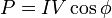 ), the same amount of power can be transmitted with a lower current by increasing the voltage. Therefore it is advantageous when transmitting large amounts of power to distribute the power with high voltages (often hundreds of kilovolts).
However, high voltages also have disadvantages, the main ones being the increased insulation required, and generally increased difficulty in their safe handling. In a power plant, power is generated at a convenient voltage for the design of a generator, and then stepped up to a high voltage for transmission. Near the loads, the transmission voltage is stepped down to the voltages used by equipment. Consumer voltages vary depending on the country and size of load, but generally motors and lighting are built to use up to a few hundred volts between phases.
The utilization voltage delivered to equipment such as lighting and motor loads is standardized, with an allowable range of voltage over which equipment is expected to operate. Standard power utilization voltages and percentage tolerance vary in the different mains power systems found in the world.
Modern high-voltage, direct-current electric power transmission systems contrast with the more common alternating-current systems as a means for the bulk transmission of electrical power over long distances. HVDC systems tend to be more expensive and less efficient than transformers. Transmission with high voltage direct current was not feasible when Edison, Westinghouse and Tesla were designing their power systems, since there was then no way to economically convert AC power to DC and back again at the necessary voltages.
Three-phase electrical generation is very common. Three separate coils in the generator stator are physically offset by an angle of 120° to each other. Three current waveforms are produced that are equal in magnitude and 120° out of phase to each other.
If the load on a three-phase system is balanced equally among the phases, no current flows through the neutral point. Even in the worst-case unbalanced (linear) load, the neutral current will not exceed the highest of the phase currents. It is noteworthy that non-linear loads (e.g. computers) may require an oversized neutral bus and neutral conductor in the upstream distribution panel to handle harmonics. Harmonics can cause neutral conductor current levels to exceed that of one or all phase conductors.
For three-phase at utilization voltages a four-wire system is often used. When stepping down three-phase, a transformer with a Delta primary and a Star secondary is often used so there is no need for a neutral on the supply side.
For smaller customers (just how small varies by country and age of the installation) only a single phase and the neutral or two phases and the neutral are taken to the property. For larger installations all three phases and the neutral are taken to the main distribution panel. From the three-phase main panel, both single and three-phase circuits may lead off.
Three-wire single phase systems, with a single centre-tapped transformer giving two live conductors, is a common distribution scheme for residential and small commercial buildings in North America. This arrangement is sometimes incorrectly referred to as "two phase". A similar method is used for a different reason on construction sites in the UK. Small power tools and lighting are supposed to be supplied by a local centre-tapped transformer with a voltage of 55V between each power conductor and the earth. This significantly reduces the risk of electric shock in the event that one of the live conductors becomes exposed through an equipment fault whilst still allowing a reasonable voltage for running the tools.
A third wire, called the bond wire, is often connected between non-current carrying metal enclosures and earth ground. This conductor provides protection from electrical shock due to accidental contact of circuit conductors with the metal chassis of portable appliances and tools. Bonding all non-current carrying metal parts into one complete system ensures there is always a low impedance path to ground sufficient to carry any fault current for as long as it takes for the system to clear the fault. This low impedance path allows the maximum amount of fault current to flow, causing the overcurrent protection device (Breakers, fuses) to trip or burn out as quickly as possible, returning the electrical system to a safe state. All bond wires are bonded to ground at the main service panel, as is the Neutral/Identified Conductor if present.
AC power supply frequencies
The frequency of the electrical system varies by country; most electric power is generated at either 50 or 60 Hz. See List of countries with mains power plugs, voltages and frequencies. Some countries have a mixture of 50 Hz and 60 Hz supplies, notably Japan.
A low frequency eases the design of low speed electric motors, particularly for hoisting, crushing and rolling applications, and commutator-type traction motors for applications such as railways, but also causes a noticeable flicker in incandescent lighting and objectionable flicker of fluorescent lamps. 16⅔ Hz power is still used in some European rail systems, such as in Austria, Germany, Norway, Sweden and Switzerland. The use of lower frequencies also provided the advantage of lower impedance losses, which are proportional to frequency. The original Niagara Falls generators were built to produce 25 Hz power, as a compromise between low frequency for traction and heavy induction motors, while still allowing incandescent lighting to operate (although with noticeable flicker); most of the 25 Hz residential and commercial customers for Niagara Falls power were converted to 60 Hz by the late 1950's, although some 25 Hz industrial customers still existed as of the start of the 21st century.
Off-shore,military, textile industry, marine, computer mainframe, aircraft, and spacecraft applications sometimes use 400 Hz, for benefits of reduced weight of apparatus or higher motor speeds.
Effects at high frequencies
A direct, constant current flows uniformly throughout the cross-section of the (uniform) wire that carries it. With alternating current of any frequency, the current is forced towards the outer surface of the wire, and away from the centre. This is because an electric charge which accelerates (as is the case of an alternating current) radiates electromagnetic waves, and materials of high conductivity (the metal which makes up the wire) do not allow propagation of electromagnetic waves. This phenomenon is called skin effect.
At very high frequencies the current no longer flows in the wire, but effectively flows on the surface of the wire, within a thickness of a few skin depths. The skin depth is the thickness at which the current density is reduced by 63%. Even at relatively low frequencies used for high power transmission (50–60 Hz), non-uniform distribution of current still occurs in sufficiently thick conductors. For example, the skin depth of a copper conductor is approximately 8.57 mm at 60 Hz, so high current conductors are usually hollow to reduce their mass and cost.
Since the current tends to flow in the periphery of conductors, the effective cross-section of the conductor is reduced. This increases the effective AC resistance of the conductor, since resistance is inversely proportional to the cross-sectional area in which the current actually flows. The AC resistance often is many times higher than the DC resistance, causing a much higher energy loss due to ohmic heating (also called I2R loss).
Techniques for reducing AC resistance
For low to medium frequencies, conductors can be divided into stranded wires, each insulated from one other, and the individual strands specially arranged to change their relative position within the conductor bundle. Wire constructed using this technique is called Litz wire. This measure helps to partially mitigate skin effect by forcing more equal current flow throughout the total cross section of the stranded conductors. Litz wire is used for making high Q inductors, reducing losses in flexible conductors carrying very high currents at power frequencies, and in the windings of devices carrying higher radio frequency current (up to hundreds of kilohertz), such as switch-mode power supplies and radio frequency transformers.
Techniques for reducing radiation loss
As written above, an alternating current is made of electric charge under periodic acceleration, which causes radiation of electromagnetic waves. Energy that is radiated represents a loss. Depending on the frequency, different techniques are used to minimize the loss due to radiation.
Twisted pairs
At frequencies up to about 1 GHz, wires are paired together in cabling to form a twisted pair in order to reduce losses due to electromagnetic radiation and inductive coupling. A twisted pair must be used with a balanced signalling system, where the two wires carry equal but opposite currents. The result is that each wire in the twisted pair radiates a signal that is effectively cancelled by the other wire, resulting in almost no electromagnetic radiation.
Coaxial cables
At frequencies above 1 GHz, unshielded wires of practical dimensions lose too much energy to radiation, so coaxial cables are used instead. A coaxial cable has a conductive wire inside a conductive tube. The current flowing on the inner conductor is equal and opposite to the current flowing on the inner surface of the outer tube. This causes the electromagnetic field to be completely contained within the tube, and (ideally) no energy is radiated or coupled outside the tube. Coaxial cables have acceptably small losses for frequencies up to about 20 GHz. For microwave frequencies greater than 20 GHz, the dielectric losses (due mainly to the dissipation factor of the dielectric layer which separates the inner wire from the outer tube) become too large, making waveguides a more efficient medium for transmitting energy.
Waveguides
Waveguides are similar to coax cables, as both consist of tubes, with the biggest difference being that the waveguide has no inner conductor. Waveguides can have any arbitrary cross section, but rectangular cross sections are the most common. With waveguides, the energy is no longer carried by an electric current, but by a guided electromagnetic field. Waveguides have dimensions comparable to the wavelength of the alternating current to be transmitted, so they are only feasible at microwave frequencies.
Fibre optics
At frequencies greater than 200 GHz, waveguide dimensions become impractically small, and the ohmic losses in the waveguide walls become large. Instead, fibre optics, which are a form of dielectric waveguides, can be used. For such frequencies, the concepts of voltages and currents are no longer used.
Mathematics of AC voltages

Alternating currents are accompanied (or caused) by alternating voltages. In English the initialism AC is commonly and somewhat confusingly used for both. An AC voltage v can be described mathematically as a function of time by the following equation:
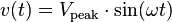 ,
,
where
 is the peak voltage (unit: volt),
 is the angular frequency (unit: radians per second)
 - The angular frequency is related to the physical frequency,
 , which represents the number of oscillations per second (unit = hertz), by the equation
  .
.
- The angular frequency is related to the physical frequency,
 is the time (unit: second).
The peak-to-peak value of an AC voltage is defined as the difference between its positive peak and its negative peak. Since the maximum value of  is +1 and the minimum value is −1, an AC voltage swings between
  and
and  . The peak-to-peak voltage, usually written as
  or
or  , is therefore
  .
.
Power and root mean square
The relationship between voltage and power is:
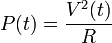 where
where  represents a load resistance
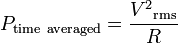
Rather than using instantaneous power,  , it is more practical to use a time averaged power (where the averaging is performed over any integer number of cycles). Therefore, AC voltage is often expressed as a root mean square (RMS) value, written as
  , because
For a sinusoidal voltage:
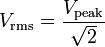
The factor  is called the crest factor, which varies for different waveforms.
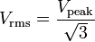
- For a triangle wave form:
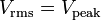
- For a square wave form:
Example
To illustrate these concepts, consider a 240 V AC mains supply. It is so called because its Root mean square value is 240 V. This means that the time-averaged power delivered is equivalent to the power delivered by a DC voltage of 240 Volts. To determine the peak voltage (amplitude), we can modify the above equation to:
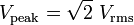
For our 240 V AC, the peak voltage Vpeak is therefore  , which is about 339 V. The peak-to-peak value
  of the 240 V AC is double that, at about 679 V.